
Hi everyone,
Welcome back to our Container blog post series. This time we will continue with part II of our Kubernetes Ingress journey! If you haven’t checked out part I you can find it here.
In this part, we will take you on a deep dive of our new Ingress infrastructure. In the first part of the series, we showed you the current setup of the stack, we discussed the weak points and listed some features which could bring improvements.
As we started working on the new stack, we mainly tried to solve the following problem: We wanted to dynamically expose a service to the outside of our clusters. In a first step only to the internal ProSiebenSat.1 network (LAN) and (in a future iteration) also to the “Internet” (WAN). It was very important for us that this feature could be completely controlled by the project/development teams aka the users of our platform. We also wanted to avoid any manual interaction from our side, the network or the security department. This means the whole “chain” needed to be fully automated. Empowering our users is key!
Now that the problem and the motivation are clear, we needed to find a place to start. This was quite difficult since we realized that there were multiple network features we needed to modify or integrate with. First, we looked at our hardware load balancer.
Hardware vs Software LB
We think that the currently used hardware load-balancer is quite stable and reliable, but it takes a lot of time to setup new virtual IP addresses (VIP) and configuring DNS names for them. A lot of manual steps are needed which are also very error prone. We looked into ways on how to automate the setup. We found out that vendor of the LB offers a REST API. Based on that, we found modules for our configuration management tool (Ansible) and other tooling around it. But there was no Kubernetes integration. The LB vendor had something on their road map, but there was no testable version available at that time. Writing our own integration was also quite a big task. The hardware LB was no real option…
So, we looked at alternatives with a native Kubernetes integration and found MetalLB. The project description says:MetaLB is a load-balancer implementation for bare metal Kubernetes cluster, using standard routing protocols.The whole project is written in Go (yeahhh) and seemed to be the perfect match for us!
MetalLB adds the capability to use the type:LoadBalancerin a Kubernetes service object. Upstream Kubernetes only support the parameter when you run it on one of the major cloud providers (GCP and Azure for example). As mentioned in Part I of the series, with a bare metal cluster you only have NodePort as an option to expose services. But MetalLB changes the rules. Let’s take a look at our WorkPress example again:

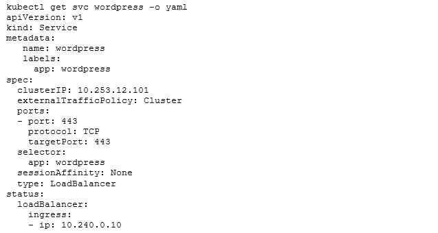
We define a service object and want to expose our app on port 443 to the outside of the cluster. The only thing that needs to be changed now, is setting the type to LoadBalancer. When you deploy the Service it will look like this:

We got two IP addresses. The CLUSTER-IP is the internal IP, which is used when another container wants to talk to our WordPress service directly. The EXTERNAL-IP is used to communicate from the outside of the cluster with the WordPress service. Feels like magic right? Where does that IP address come from? Who or what did the assignment?

In the picture above we will ignore the upper left part for now and focus on how MetalLB assigns IPs for services. First, we need to define a pool with IP addresses which MetalLB can manage. In our case we talked to our network department and they gave us some IP ranges which are not in use. It’s also possible to define multiple pools per environment. This can be pretty helpful if you want to separate workloads. For now, we stick with one pool though.
When looking at MetalLB we have two components: The first one is the controller. It runs as a Kubernetes deployment with at least two replicas to make it more resilient against failures. The job of the controller is to hook into the Kubernetes API and watch for services which have the type: Loadbalancer property set. It is also doing IP address management (IPAM) for us. The controller checks the status of the services and knows which IP addresses are currently in use and which one are free for assignment. It assigns an address by manipulating the Kubernetes Service object:
On the last three lines you will see, that there is a new status field. If this is empty, the controller will search for a free IP in the configured pool and will assign it to the service. That’s the easy part. Currently only our Kubernetes cluster knows something about the assigned IPs. We need to find a way to publish them and make them reachable from the outside.
MetalLB offers two solutions for this problem:
- Layer 2 mode (ARP/NDP): In Layer 2 mode, one machine in the cluster takes ownership of the service and uses standard address discovery protocols (ARP for IPv4 and, NDP for IPv6) to make those IPs reachable on the local network. From the LAN’s point of view, the announcing machine simply has multiple IP addresses.
This is the easiest setup and just works out of the box. The problem with that method is, that it’s not very reliable for production use cases. As mentioned above one machine in the cluster takes ownership. In a production environment, you want to balance the network requests to multiple machines for multiple reasons:
- You want to be able to scale, because, it could be that a single network interface cannot handle the load of the service
- To make the service more reliable against any kind of failures (server, network, energy outages).
Let’s take a look at the alternative:
- BGP: In BGP mode, all machines in the cluster establish BGP peering sessions with nearby routers that you control and tell those routers how to forward traffic to the service IPs. Using BGP allows for true load balancing across multiple nodes and fine-grained traffic control thanks for BGPs policy mechanisms.
That method sounds very good for our production use case. But wait … What is BGP?
For all of you, who are not working with BGP every day. Wikipedia says:
And what a surprise, we aimed for the BGP mode. It adds complexity but it also provides flexibility, scalability and reliability. BGP also has a wide adoption, because it’s the standard for peering and exchanging routing information on the internet. For example: BGP is used to exchange routing information between two internet service providers (ISP) if they want to talk to each other and connect their customers. We also thought that most modern enterprise network devices should support and work with BGP.
As you can see in the picture above, the MetalLB Speaker will handle the distribution of routing information. The Speaker runs as a DaemonSet, which means Kubernetes will make sure that one Speaker-Pod is running on every node in the cluster. The Speaker will also hook into the Kubernetes API and will look for services with type:Loadbalancer.
Only services with an already assigned IP (from the MetalLB Pool) will be distributed.
To speak BGP we also need a so called “upstream” device. This could potentially be anything that can talk BGP (a router, a reflector, a firewall or a piece of software). In our case we already had a firewall in our Layer 2 network (as a default gateway). The simplest solution was to use the firewall as a peering device. The MetalLB config for this looks like this:

In the config above you can see that we defined one pool 10.245.0.0/16 and gave it the name lan. In addition to that, we needed to tell MetalLB in which mode this pool should be handled. We can also add new pools for additional use cases later. When we want to add new pools, we need to talk to the network department first, since we need unused network segments. This is important to avoid IP conflicts inside the LAN. In the next section we defined the BGP peering information. We used the IP address of the peering device, which is our default gateway. Next, we needed to define AS numbers (ASNs). They are used to identify which routers are published by which system. Every Kubernetes cluster will have another unique ASN. And that’s it from the Kubernetes side! The final step: the upstream device needs to be configured by our network department with a list of peering clients (all nodes of one cluster) and the ASNs.
When the Speaker starts, it will try to establish a BGP session with the upstream device: Note: Establishing a session involves more steps. We will skip the details. If someone wants to know more about it check out this article.
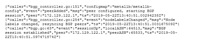
After the session is up and running the Speaker will start to send route announcements:

On the upstream device side, this will result in a 10.240.0.10/32 route. This route will point to the IP address of the node on which the Speaker (which announced the route) runs on.
So now that our routes get published to the upstream device, the next question was: Are we done now? Can we access the IP addresses? Sadly, the answer was no. Our upstream device didn’t know what to do with them. We needed to find a way to forward the routes to the core routers inside the ProSiebenSat.1 network. The problem was that these routers only speak Open Shortest Path First (OSPF). Our colleague Andreas Mang needed to find a solution for translating BGP into OSPF. After the translation was in place the routing worked like a charm!
We were able to connect to our announced IP addresses. But we had two more challenges to master:
10 years old RFCs and enterprise network products.
Before we started to deeply integrate with MetalLB we had to move to another upstream device with better performance. We migrated over and nothing was working anymore. MetalLB cloud not establish a connection.
On the upstream device we saw:
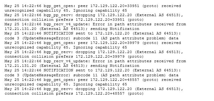
After searching through the manual of the upstream device we found out that capability 65 means:

What does that mean? Well BGP is a very old protocol (like most of the basic protocols used in the internet) and it was extended quite a view times. One extension is RFC 4893 – BGP Support for Four-octet AS Number Space , which was published in 2007. This RFC was updated again in 2012 with RFC 6793 . With the old version of the protocol you could use (0 – 65535) as an ASN. Since so many people used BGP the ASNs quickly got exhausted. So RFC 4893 extended the space to 4 byte ASNs which could provide 2^32 or 4,294,967,296 autonomous system numbers.
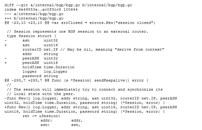
Our problem was, the upstream device which we wanted to peer with had an older software release that didn’t have RFC 4893 or 6793 implemented. Some of you might think we could use 64513 as our ASN. That should be in the old range, right? It’s definitely in the old 2 byte range, but MetalLB says: “Hey it’s 2019! I will send 4 byte ASN, regardless if people configure a 2 or 4 byte ASN”. At this point we were a little lost, since the support vendor of the upstream device couldn’t come up with a solution. They promised us that a fix will be in next version which will come very soon™️ (whatever that means ;)) The only option left, was to patch MetalLB and reduce the ASN size to 2 bytes. That was quite tricky. To get an impression, here is a little snippet of the git patch file:
The next challenge was to add reliability and scalability to the solution. The magic network buzz word here was Equal-cost-multi-path-routing.
To achieve reliability and scalability we needed to spread all incoming requests to all available paths. Without ECMP the upstream device would route all incoming requests to the same path. If that path would become unavailable (for example: the server crashes) another path would be chosen. With ECMP, the upstream device will choose different paths for each request. The load is spread evenly between all paths.
While testing we quickly noticed that with the default settings of a Kubernetes Service, every node in the cluster was a valid path for the firewall. After investigating a little we found out that this is controlled by the externalTrafficPolicy.
External Traffic Policy
Packages sent to a Service with type: LoadBalancer and externalTrafficPolicy: Cluster are source NATed by default, because all schedulable Kubernetes nodes in the Ready state are eligible for load balancing traffic. If packets arrive at a node without an endpoint, the system proxies it to a node with an endpoint, replacing the source IP of the package with the IP of the node.

This is what happens:
- Client sends packet to node2
- Node2 replaces the source IP address (SNAT) in the packet with its own IP address
- Node2 replaces the destination IP on the packet with the Pod IP
- Packet is routed to node1 and then to the endpoint
- The Pod’s replay is routed back to node2
- The Pod’s replay is sent back to the client
That means, if you have only one replica of a Deployment running inside the cluster, the possibility is very high, that the request from the outside will hit a node that doesn’t run the Pod. We would also add a few network hops here, which would add latency. To avoid this, Kubernetes ships with another external Traffic Policy which is called Local.

When local is set this happens:
- Client sends packet to node2, which doesn’t have any endpoints
- Packet is dropped
- Client sends packet to node1, which does have endpoints
- Node1 routes packet to endpoint with the correct source IP
The good thing is, that MetalLB is very clever. When you have a Service with that policy, the Speaker will only announce the route to the Service, if the Pod which is connected to the Service, also runs on this node. That means, we never have the case that requests will be sent to nodes which don’t have an endpoint for the requested Service. This will boost performance, since there are no additional hops when reaching the service.
With the current MetalLB configuration, we have created the groundwork for a software defined ingress network. But we are still missing some important functions. We currently only have IP addresses and no DNS for our dynamically created IPs.
We will explain how we solved the DNS problem and show our new Ingress controller in the third part of the series.
As always, if you have question other comments, feel free to send us a mail at peo@p7s1.net. Cheers The PEO team.